I have created a program with the code from your page and it does not work
Check your code. If it still doesn’t work, check your code again. If it still doesn’t work then email me. The code presented here has been used by several student’s classes, is used in more than a dozen products and has been carefully tested by more than 30 people. The chance that the problems you’re experiencing are in the part of the code presented here is slim. The most common error is about data types. The algorithms presented here expect the data to be in 32bit IEEE754 floating point format, which is the standard format for single precision floating point on today’s desktop computers. However, the data stored in your sound file will most probably be of a different format. Make sure you are aware of the differences and the conversion needed before you assume the error is in my part of the code. If in doubt, use my MiniAIFF library to access your sound files, it takes care of all the necessary file and data conversion related details.
I am a musician and wish to start programming my own algorithms. Where do I start?
First, you buy a computer and some software development tools, like CodeWarrior. Then you should start learning a modern programming language, like C and C++. It is a good idea to make yourself familiar with some free audio/plug in SDKs, like VST. After that, you should read some basic DSP textbooks, like Sophocles Orfanidis “Introduction to Digital Signal Processing”, or Oppenheim and Schafer “Discrete Time Signal Processing”. The book from Rick Lyons comes to mind, which has been favorably mentioned by many students. After that, if you’re still convinced this is what you want, delve into the DSP literature, take an online course at Bores.com and expand your knowledge according to your preferences.
May I use your tutorials/code in my commercial/non-commercial application, thesis, lecture, etc.?
Yes. Please make sure, however, that you give credit where credit is due.
As I was reading the section on the lowest and highest frequencies needed to recreate an input signal, I noticed a discrepancy that I still cannot figure out. You say that the lowest frequency is the frequency that completes exactly half its period in the signal. In mathematical terms that would be: fmin = pi rad * 1 / NT sec = pi / NT rad/sec N = number of samples T = sampling interval However, the DFT defintion given at: http://ccrma.stanford.edu/~jos/mdft/DFT_Definition.html uses 2pi / NT rad/sec. Why does the DFT definition not use the minimum frequency?
The discussion on my page refers to a real-valued transform, like the sine or cosine transform, before it actually introduces the DFT. This makes sense because the complex arithmetics required for the DFT would further complicate things and make them less intuitive. The DST and DCT have a twice as dense “frequency grid” spacing than the DFT, which is why JOS is introducing the factor 2 (btw., if you take a close look on the actual DFT in listing 1.2 on my page you’ll see that it is also using the factor 2 spacing)
I read your article ‘The DFT ‘à Pied’. In the article, you state: “…every signal, however complex, can be represented by a sum of sinusoid functions that are individually mixed”. I was curious to whether sinusoids could be replaced with square waves. Would the results from this square wave DFT differ substantially from a sinusoid DFT, and if they’re the same, how come no-one seems to have developed a fast integer FFT around the concept? Is there something I’m missing here?
Yes you can indeed use other functions than the sin/cos basis functions, but they need to have certain mathematical properties in order to work for this purpose. Also, you cannot simply replace them. Even though the results might seem similar at first glance, try inverting the transform to check if you get back your original waveform – you will not. Using square waves (or triangular waves, trapezoidal waves, sawtooth waves) requires some additional work, most notably the introduction of the Moebius function. One example:
A square wave can be approximated by the sum of sinusoids mixed at the following ratios:
sqr(x) = sin(x) + (1/3)sin(3x) + (1/5)sin(5x) + (1/7)sin(7x) + (1/9)sin(9x)… =
sqr(x) = SUM[k=1…N] (1/(2k-1))sin((2k-1)x)
Conversely, a sine wave can be approximated by the series of square waves starting with:
sin(x) = sqr(x) – (1/3)sqr(3x) – (1/5)sqr(5x) – (1/7)sqr(7x) + (0/9)sqr(9x)… =
sin(x) = SUM[k=1…N] (mu(2k-1)/(2k-1))sqr((2k-1)x)
The sign of the square wave components is determined by the Moebius function mu(), that’s the reason for the 9x component being zero. 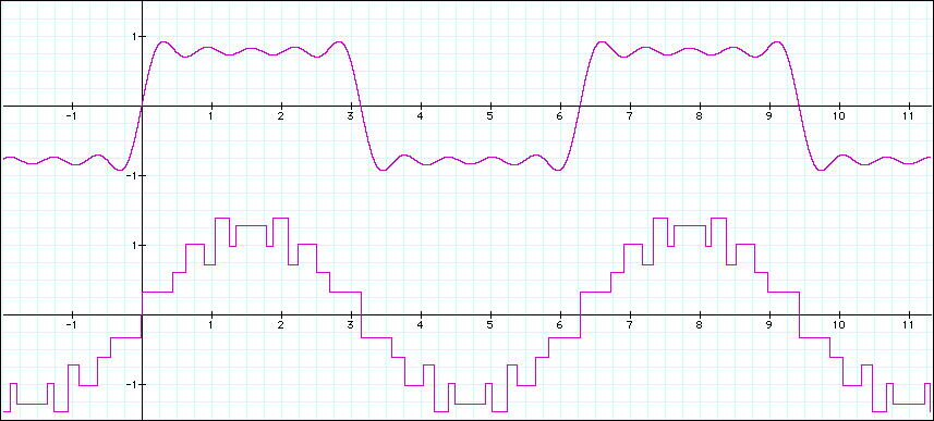
Using other functions than the sin/cos pairs can be important, for example if you only have square wave generators to reconstruct the signal. Calculating the Fourier transform coefficients from the square wave coefficients is possible, so you can also do filtering and synthesis in the square wave domain. There is a research area named “arbitrary waveform analysis” or “common waveform analysis” (since square, sawtooth etc. waves are “common waveforms” in electronics) that deal with the topic. Indeed, transforms based on waveforms other than sin/cos waves are available.
Recommended further reading: Y. Wei, Q. Zhang: “Common Waveform Analysis: a new and practical generalization of Fourier analysis”, Kluwer Academic Publishers, Boston, MA, 2000.
I’m trying to reproduce the numbers you list in the tables accompanying your “Pitch Shifting Using the Fourier Transform” article, but I can’t figure out how to calculate the frequency values.
The estimated true frequency F from the bin phase p (at bin i) is calculated from the overlap factor s, the sample rate R and the size of the DFT frame size N as:
Fi = (R/N) * (i + pi*s/(2?))
Explanation: The frequency resolution in Hz is given by R/N. Two neigbouring bins are therefore R/N Hz apart. The phase of a bin is limited by the arc tangent function to the interval ±?/2. We can expand this interval by taking the sign into account when calculating the phase angle, therefore our maximum phase deviation is ±?. This means that the phase of a bin can vary by ±? depending on its frequency deviation from the bin’s center frequency.
Taking the overlap into account: the more overlap we have, the larger is our frequency area that the bin frequency can sweep since there is less time between the individual measurements (DFT frames) and we therefore get a higher resolution within the ±? interval. We could also say that the same deviation in phase means double deviation in frequency if our DFT frames are twice as densely spaced.
I think there might be a problem with you pitch shifter when you have two or more frequency components that fall into the same bin. For example: 1) If you have 2 freq. components that fall into separate FFT frequency bins, you are OK. Each freq. component will be shifted by the same ratio. (ex. 10%) 2) If you have 2 freq. components that fall into the same FFT frequency bin, but they appear at different times, you are still OK, each freq. component will proportionally be shifted by the same ratio. 3) However, if you have 2 freq. components that fall into the same FFT frequency bin, and they happen at the same time, BOTH COMPONENTS WILL BE SHIFTED BY THE SAME AMOUNT, which means, different ratios. Is this a known issue?
Indeed, your observation is correct – this is related to the resolution properties of the DFT.
For the case you mention, there are two different scenarios:
1) Consider two closely spaced sinusoids in your input signal that fall into the same bin, for example at 500 and 505 Hz. In this case, they will be shifted both by the same amount (doubling the frequency will move them to 1000 and 1005 Hz instead of 1000 and 1010 Hz) because scaling the bin frequency just heterodynes (frequency shifts) everything within the bin bandwidth. The net effect of this shift might not be prominent enough to be noticed by the listener – depending on the DFT size (and the resulting bin frequency resolution). For small DFT sizes however this might cause the resulting sound to be inharmonic and metallic.
2) Scaling two closely spaced frequencies that are initially NOT located within the same bin might move them closer together for a bin frequency scaling factor < 1.0 which might eventually cause them to fall into the same bin. In that case, the net phase effect should be calculated differently from the way it is done in the code now. I’ve not taken this into account in the present version to keep the code readable.
One might also argue that closely spaced frequencies will cause a low frequency modulation (“beating”) in the signal, which will result in yet another bin getting involved in the process. Therefore, the pitch shifter introduced at the DSP Dimension web site is actually a simplified version of a much more complex process if you really want to do it “right” 😉
 © 2026 Zynaptiq GmbH, All Rights Reserved. Use or reproduction of materials from this site prohibited unless explicitly granted in writing.
How to get amplitude from wav ??
fabs(sample) is amplitude.
I am an electronics engineer. I have worked mostly in the image processing domain, and have very less experience in the audio domain but that is where i want to work. could you tell me how i could go about that?