 With the increasing speed of todays desktop computer systems, a growing number of computationally intense tasks such as computing the Fourier transform of a sampled audio signal have become available to a broad base of users. Being a process traditionally implemented on dedicated DSP systems or rather powerful computers only available to a limited number of people, the Fourier transform can today be computed in real time on almost all average computer systems. Introducing the concept of frequency into our signal representation, this process appears to be well suited for the rather specialized application of changing the pitch of an audio signal while keeping its length constant, or changing its length while retaining its original pitch. This application is of considerable practical use in todays audio processing systems. One process that implements this has been briefly mentioned in our Time Stretching and Pitch Shifting introductory course, namely the “Phase Vocoder”. Based on the representation of a signal in the “frequency domain”, we will explicitely discuss the process of pitch shifting in this article, under the premise that time compression/expansion is analogous. Usually, pitch shifting with the Phase Vocoder is implemented by changing the time base of the signal and using a sample rate conversion on the output to achieve a change in pitch while retaining duration. Also, some implementations use explicite additive oscillator bank resynthesis for pitch shifting, which is usually rather inefficient. We will not reproduce the Phase Vocoder in its known form here, but we will use a similar process to directly change the pitch of a Fourier transformed signal in the frequency domain while retaining the original duration. The process we will describe below uses an FFT / iFFT transform pair to implement pitch shifting and automatically incorporates appropriate anti-aliasing in the frequency domain. A C language implementation of this process is provided in a black-box type routine that is easily included in an existing development setup to demonstrate the effects discussed.

1. The Short Time Fourier transform
As we have seen in our introductory course on the Fourier transform, any sampled signal can be represented by a mixture of sinusoid waves, which we called partials. Besides the most obvious manipulations that are possible based on this representation, such as filtering out unwanted frequencies, we will see that the “sum of sinusoids” model can be used to perform other interesting effects as well. It appears obvious that once we have a representation of a signal that describes it as a sum of pure frequencies, pitch shifting must be easy to implement. As we will see very soon, this is almost true.
To understand how to go about implementing pitch shifting in the “frequency domain”*, we need to take into account the obvious fact that most signals we encounter in practice, such as speech or music, are changing over time. Actually, signals that do not change over time sound very boring and do not provide a means for transmitting meaningful auditory information. However, when we take a closer look at these signals, we will see that while they appear to be changing over time in many different ways with regard to their spectrum, they remain almost constant when we only look at small “excerpts”, or “frames” of the signal that are only several milliseconds long. Thus, we can call these signals “short time stationary”, since they are almost stationary within the time frame of several milliseconds.
Because of this, it is not sensible to take the Fourier transform of our whole signal, since it will not be very meaningful: all the changes in the signals’ spectrum will be averaged together and thus individual features will not be readily observable. If we, on the other hand, split our signal into smaller “frames”, our analysis will see a rather constant signal in each frame. This way of seeing our input signal sliced into short pieces for each of which we take the DFT is called the “Short Time Fourier Transform” (STFT) of the signal.
2. Frequency Resolution Issues
To implement pitch shifting using the STFT, we need to expand our view of the traditional Fourier transform with its sinusoid basis functions a bit. In the last paragraph of our article on understanding the Fourier transform we have seen that we evaluate the Fourier transform of a signal by probing for sinusoids of known frequency and measuring the relation between the measured signal and our reference. In the article on the Fourier transform, we have chosen our reference frequencies to have an integer multiple of periods in one DFT frame. You remember that our analogy was that we have required our reference waves to use the two “nails” that are spanned by the first and last sample in our analysis “window”, like a string on a guitar that can only swing at frequencies that have their zero crossings where the string is attached to the body of the instrument. This means that the frequencies of all sinusoids we measure will be a multiple of the inverse of the analysis window length – so if our “nails” are N samples away, our STFT bins will have a spacing of sampleRate/N Hertz. As a result, this concept imposes an artificial frequency grid on our analysis by requiring the reference frequencies to be an integer multiple of our signal window in period to make them seamlessly fit into our analysis frame.
This constraint will have no consequence for the frequencies in our signal under examination that are exactly centered on our reference frequencies (since they will be a perfect fit), but since we are dealing with realworld signals we can’t expect our signal to always fulfill this requirement. In fact, the probability that one of the frequencies in our measured signal hits exactly one of our STFT bins is rather small, even more so since although it is considered short time stationary it will still slightly change over time.
So what happens to the frequencies that are between our frequency gridpoints? Well, we have briefly mentioned the effect of “smearing”, which means that they will make the largest contribution in magnitude to the bin that is closest in frequency, but they will have some of the energy “smeared” across the neighbouring bins as well. The graph below depicts how our magnitude spectrum will look like in this case.
 |
 |
||
|
|
As we can see from the above graph, when the measured signal coincides with a bin frequency it will only contribute to that bin. If it is not exactly centered on one of the bin frequencies, its magnitude will get smeared over the neighbouring bins which is why the graph in 2.2. has such a broad basis while the graph in 2.1 shows just a peak at bin 50.
The reason why I’m outlining this is that this effect is one of the key obstacles for most people who try to implement pitch shifting with the STFT. The main problem with this effect isn’t even really the magnitude spectrum, since the magnitude spectrum only tells us that a particular frequency is present in our signal. The main problem, as we will see in a minute, is the bin phase.
3. From Phase to Frequency
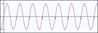
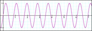
We have learned in our article on the Fourier transform that – with proper post-processing – it describes our signal in terms of sinusoids that have a well defined bin frequency, phase and magnitude. These three numbers alone characterize a sinusoid at any given time instant in our transform frame. We have seen that the frequency is given by the grid on which we probe the signal against our reference signal. Thus, any two bins will always be sampleRate/N Hertz away from each other in frequency. We have seen above that in the case where our measured signal coincides with the bin frequency everything is smooth – obviously it will have a frequency that is a multiple of sampleRate/N. However, what should we expect to see when it is not a multiple of sampleRate/N in frequency? Take a look at the following graph:
 |
 |
||
|
|
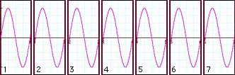
These two graphs look pretty normal, except that we see that the two signals obviously do not have the same frequency – the one depicted in 3.2 is of higher frequency than our sine wave in 3.1. We have announced that we will use short frames for analyzing our signals, so after splitting it up into our analysis frames it will look like this:
 |
 |
||
|
|
Our sampled signal from 3.1 that is exactly centered on a bin frequency nicely splits up into seven successive analysis frames. In each frame, the waveform starts out at zero and ends with zero. To put it more exactly: in each frame, the measured signal starts at the same point in its cycle, that is, it starts with the same phase.
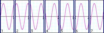
Our sampled signal from 3.2 that is somewhere between two bins in frequency does not nicely split into our seven successive analysis frames. In each frame, the waveform has a clearly visible phase offset, ie. it begins at a different point in its cycle. The more off-center it is in frequency from the bin frequency, the larger this phase offset will be. So, what we see here is that while signals whose frequency is exactly on a bin frequency have the same phase offset in each frame, the phase of signals that have a frequency between two bin frequencies will have an offset that is different with each frame. So, we can deduce that a difference in phase offset between two frames denotes a deviation in frequency from our bin frequencies.
In other words: if we measure our k-th sinusoid with its bin magnitude, frequency and phase, its magnitude will denote to what extent that particular frequency is present in our signal, the frequency will take on its bin frequency and the phase will change according to its deviation from that bin frequency. Clearly, since we now know that a change in phase with each frame means a deviation in frequency from the bin frequency, we could as well use the phase offset to calculate the sinusoids’ true frequency. So, we can reduce the three numbers we get back from our post-processed analysis for each sinusoid, namely bin magnitude, bin frequency and bin phase to just magnitude and true frequency**.
Mathematically, computing the change of a parameter is known as differentiation (which means “taking the difference”, or, in the case of a function, computing the functions’ derivative), since we need to compute the difference between the current parameter value and the last parameter value, ie. how much it has changed since our last measurement. In our specific case, this parameter is the bin phase. Thus, we can say that the k-th partials’ deviation in frequency from its bin frequency is directly proportional to the derivative of the bin phase. We will use this knowledge later to compute the true frequency for that partial.
4. About The Choice of Stride
As if this wasn’t enough to consider, we also have to worry about another problem. Simply splitting the signal into successive, non-overlapping frames like we have used in our above illustration does not suffice. For several reasons, most importantly the windowing*** that needs to be done to reduce the “smearing” of the bin magnitudes, and in order to be able to uniquely discriminate the bin phase derivative without ambiguity, we need to use overlapping frames. The typical overlap factor is at least 4, ie. two adjacent windows overlap by at least 75%. Fortunately, the significance of the frame overlap on bin phase and its derivative is easy to calculate and can be subtracted out before we compute the true bin frequency. We will see how this is done in the source code example below. Actually, it is pretty unspectacular since we simply calculate how far our bin phase derivative is expected to advance for a given overlap and then subtract this offset from our phase difference prior to computing the k-th partials’ true frequency.
The other, more important thing we need to consider which is associated with this, however, is that the choice of the overlap affects the way our true partial frequencies are discriminated. If we have frames that are overlapping to a great extent, the range in which the true frequency of each of the sinusoids can vary will be larger than if we choose a smaller overlap.
To see why this is the case, let us first consider how we actually measure the bin phase. As we can see from our source code example, we use the arc tangent of the quotient of sine and cosine part (in the source code example, they are referred to as imaginary (im) and real (re) part of each bin for mathematical terminology reasons). The sign of the sine and cosine parts denote the quadrant in which the phase angle is measured. Using this knowledge we can assume that the bin phase will always be between -π and +π at any time, since this is the range of our atan2() functions’ return value. Therefore, the increase in phase between any two adjacent frames has an upper limit, with a negative angle difference denoting a negative deviation from the bin frequency and a positive angle difference denoting a positive deviation in frequency from the bin frequency. To make sure the phase difference value is centered around 0 (ie. measured as an absolute value against the origin, that is, always in the range ±π which we need in order to measure the frequency deviation) we wrap the phase difference back into our ±π interval. This is necessary since the phase offset we subtract out to make up for the overlap may cause our phase difference to be outside that interval.
Now, in the simple case that any two adjacent frames will not overlap and we know we have an interval of ±π to denote the deviation in frequency of one partial from our bin frequency, we would only be able to discriminate a frequency deviation that is ±0.5 bins since this is the maximum advance in phase between two frames we can unambiguously discriminate in this case. When the frequency of our measured signal crosses the boundary between the two adjacent STFT bins, the phase difference will wrap back to the beginning of our interval and that partials’ frequency will be far away from the actual frequency of our input sinusoid.
Pass #1: 2411.718750 Hz (bin 112.0):
See FAQ on how I got these numbers |
Pass #2: 2416.025391 Hz (bin 112.2):
See FAQ on how I got these numbers |
Pass #3: 2422.270020 Hz (bin 112.49):
See FAQ on how I got these numbers |
We can see that when we start out at exactly the frequency of bin 112 as shown in the table of pass #1, the true frequencies for all channels that are significant (ie. have nonzero magnitude) are correctly centered on their bin frequencies as is to be expected considering we use a frequency that is a perfect fit. The 0.5 value for the magnitude of bin 111 and 113 is due to the windowing we use. When we increase the frequency of our measured signal in pass #2 to be 20% away from the 112th bin’s frequency, we see that bin 112 correctly tracks our signal, while the bin above, towards which the frequency moves, goes even farther away from the correct frequency although its magnitude increases. This is because it wraps back in its interval and actually goes into the opposite direction! This gets even more evident in pass #3 which shows that the 113th bin (which should actually be closer to the true frequency of our measured signal now according to its magnitude) goes even more into the wrong direction.
Pass #4: 2422.485352 Hz (bin 112.5):
See FAQ on how I got these numbers |
In pass #4, the frequency of our measured signal is now halfway between two bins, namely between bin 112 and 113. We can see this from the bin magnitude, which reflects this fact by having an identical value for these two bins. Now bin 113 takes on the correct frequency, while bin 112 wraps back to the beginning of its interval (from 3.079 =~ 3.1415 [+π] to -3.1415 [-π]).
For comparison, here’s how the numbers look like when we use an overlap of 75%:
Pass #5: 2422.485352 Hz (bin 112.5), 4x overlap:
See FAQ on how I got these numbers |
When we want to alter our signal (which we need to do in order to achieve the pitch shifting effect), we see that with no overlap we easily run into the scenario (depicted in pass #4 above) where on resynthesis we have two sinusoids of equal amplitude but actually one bin apart in frequency. In our case, this would amount to a difference in frequency of about 21.5 Hz. Thus, when putting our signal back together we would have two sinusoids that are apparently 21.5 Hz apart where we had one single sinusoid as input. It is not surprising that the synthesized signal will not sound very much like the original in this case. Clearly, when we just resynthesize the signal without pitch shifting we can expect that these effects will cancel out. However, this no longer holds in the case when we alter our signal by scaling the partial frequencies – we would expect that this will introduce an audible error in our signal since the wrapping will now happen at a different rate.
When we look at pass #5 which uses a 4x overlap (ie. 75%), we see that all adjacent sinusoids down to a bin magnitude of 0.17 (approx. -15 dB) have about the same frequency, the error can be considered negligible. The next sinusoid that does not have the correct frequency is approximately -32dB down, which is much better than in the case where we used no overlap. Thus, we would expect this to sound considerably better. As you can easily verify with the code below, this is indeed the case.
Summarizing the above, we see that choosing a larger overlap, which is actually oversampling our STFT in time, increases our ability to estimate the true frequency of our measured sinusoid signal by making the range in which each sinusoid can deviate from its bin frequency larger: a range of ±1/2 period (±π) has a different meaning when we space our frames more closely, as the same phase difference for 2x and 4x overlap means twice as high a frequency deviation in the 4x case than in the 2x case. Thus, the closer we space our frames, ie. the more they overlap, the better we will be able to determine our true sinusoid frequencies in our measured signal. Of course, the computational cost will also increase, since we need to perform twice as many STFTs when we increase our overlap from 50% to 75%.
As a consequence for its practical implementation we now see why we need an overlap that is sufficiently large: if we have a measured signal whose frequency is between two bins, we will have two bins with large magnitude. However, since the true frequency is somewhere between the two bins and each bin can only deviate by a fixed amount depending on the overlap, we may have two prominent sinusoids that play at two different, yet close frequencies. Even worse, if the true frequency of the sinusoid is between the two bins k and k+1 like in our example shown in pass #4, the frequency of the sinusoid k will move farther away from the true frequency since its phase difference will – trying to lock on the frequency of the input sinusoid – wrap into the opposite branch. This will produce audible beating in our resynthesized sound and thus scramble our result. A 75% overlap remedies this situation: adjacent sinusoids down to an acceptable magnitude are now able to always lock on the true frequency without wrapping – they have become more “flexible” in frequency which will yield a considerably better sonic quality. As a result, the beating is almost completely gone.
5. Shifting the Pitch
Once we have mastered the difficulties of calculating the true partial frequencies for our bins, shifting the pitch is comparably easy. Let’s look at what we now have gained after calculating the partials’ true frequencies: first, we have an array of numbers that holds our magnitude values. When we scale the pitch to become sharp, we expect our magnitude array to expand by our pitch shift factor towards the upper frequency end. Likewise, when we scale our pitch to become flat, we expect our magnitude spectrum to contract towards the low frequency end. Obviously, the actual magnitude values stored in the array elements should not change, as a pure sine of -2dB at 1000 Hz is expected to become a pure sine of -2dB at 500 Hz after a 0.5 x pitch shift. Second, we also have an array that holds the true frequencies of our partial sinusoids. Like with the magnitude spectrum, we would also expect our frequency spectrum to expand or contract according to the scale factor. However, unlike the magnitude values, the values stored in our frequency array denote the true frequencies of our partials. Thus we would expect them to change according to the pitch shift factor as well.
In the simplest of all cases, we can just put the scaled partial frequencies where they belong, and add the magnitudes for the new location together. This will also preserve most of the energy contained in the input.
We also see why pitch shifting using this procedure automatically includes anti-aliasing: we simply do not compute bins that are above our Nyquist frequency by stopping at fftFrameSize2. This does not even need an additional processing step.
6. Back to where we came from…
To obtain our output signal, we need to undo all steps that we took to get our magnitude and frequency spectra. For converting from our magnitude and frequency representation back to bin magnitude, bin frequency and bin phase we follow the same path back that brought us here. Since the sine and cosine parts of the STFT are periodic and defined for all time and not just in a certain interval, we need not care for phase rewrapping explicitely – this is done by the basis functions automatically at no extra cost. After taking the inverse Fourier transform (for which we use the routine smbFft() from our DFT à Pied article) we string our overlapping frames together at the same choice of stride to get back our pitch shifted signal.
7. The Code
So how do we actually implement it in software? First, we obtain our current STFT frame from a FIFO queue. This is required since we don’t want to be forced to use a particular input buffer size – this way we can process all data independent of the FFT frame size we use for the actual pitch shifting. The data is windowed and [re, im] interleaved into the gFFTworksp array where it gets transformed by the Fast Fourier Transform algorithm smbFft(). This FFT algorithm isn’t particularly efficient, it’s just there to demonstrate how to use the routine and to make it compile without modification. You might replace it by your flavor of the FFT later. smbFft() can be found at the end of our DFT à Pied article.
Now we’re equipped with the complex output for the positive and negative frequencies of our DFT bins. Note that we only need the positive frequencies as our original signal was purely real. We convert them to magnitude and phase by rectangular to polar conversion and obtain the instantaneous bin frequency from the phase difference between two adjacent STFT frames. From that we deduce and compensate for the expected, frequency dependent advance in phase between two adjacent frames and obtain the true partial frequency. After doing the actual pitch shifting process described in (6) above, we undo our frequency domain wizardry and then transform to get back to our newly created time domain sequence. After de-interlacing the [re, im] array, windowing and rescaling we put the data into the output queue to make sure we have as much output data as we have input data. The global I/O delay is inFifoLatency samples (which means that the start of your output will contain that many samples of of silence!) – this has to be taken into account when we write the data out to a file.
Worth noting: The routine smbPitchShift() uses static variables to store intermediate results. This is rather inelegant and should be replaced by appropriately allocated and initialized memory instead. Note also on routine parameters: The routine smbPitchShift() takes a pitchShift factor value which is between 0.5 (one octave down) and 2. (one octave up). A value of exactly 1 does not change the pitch. If you need a wider pitch shift range you need to tweak the code a bit. numSampsToProcess tells the routine how many samples in indata[0… numSampsToProcess-1] should be pitch shifted and moved to outdata[0 … numSampsToProcess-1]. This can be any number of samples. The two buffers can be identical (ie. it can process the data in-place). fftFrameSize defines the FFT frame size used for the processing. Typical values are 1024, 2048 and 4096. For a sample rate of 44.1kHz, a value of 1024 is generally fine for speech, while a value of 2048 works well with music. It may be any value <= MAX_FFT_FRAME_LENGTH but it MUST be a power of 2 unless you use an FFT that can deal with other frame sizes as well.
8. Conclusion
In this article we discussed a way to use the STFT for changing the perceived pitch of an audio signal by representing it as a sum of sinusoids and scaling the frequency of these sinusoids. We have detailed the steps necessary to convert the raw output of a discrete Fourier transform to a musically meaningful representation by making the STFT partials lock and track the actual harmonics in our input signal to the extent permitted by this ‘generic’ representation. We have then used this data to alter the pitch of the underlying signal. C source code for implementing the above process in a black-box type routine that takes and returns any number of sample values as provided by the calling application is given in Appendix A below, subject to the terms set forth in the WOL Wide Open software License.
Have fun!
Stephan M. Bernsee, The DSP Dimension
*) The term “frequency domain” is a common yet somewhat imprecise nickname widely used for the raw output of the Fourier transform. We will use this term in this article only in conjunction with the notion of frequency as introduced by the pitch shifting process implemented below, where it denotes an array of numbers containing the true frequencies of our partials derived by properly post-processing the Fourier transform output.
**) This steps assumes an initial condition for the bin phases which the computation of the sinusoids’ true frequency is based on. In our discussion we will always assume the initial phases are set to zero as the phase difference of the second to the first frame will make successive frequency estimates take on appropriate phase values.
***) Windowing is a process where the signal is faded in and out during one STFT frame in a particular manner. This suppresses the energy that gets smeared over adjacent bins to some extent, since an in such a way tapered signal has less frequencies generated by the discontinuity at the frame boundaries. The interested reader is referred to Chris Bores’ course for a detailed introductory explanation of windowing.
![]()
 © 2026 Zynaptiq GmbH, All Rights Reserved. Use or reproduction of materials from this site prohibited unless explicitly granted in writing.
Thanks for this great tutorial! One thing i don’t really get is the cause of windowing the signal two times…
and what is the matter for gOutputAccum[k] += 2.*window*gFFTworksp[k][0]/(fftFrameSize2*osamp); ? Why do you multiplicated the left part the divisor with 2 and why does the right part consist of (fftFrameSize2*osamp) and not just osamp?
Sorry if this is a dumb question 😉
There may be stupid answers but I don’t think that I ever heard a dumb question.
First, about windowing: you need to window the signal twice because in the case of any “realworld” signal the bin phases in your signal will lose sync after some time. IOW, upon resynthesis the individual bin phases are not aligned in the same way they were before the pitch was changed – this will introduce reverberation into the signal and will also smear any transient signal in time. An impulse will be spread out over several milliseconds and the same is true for your input window. So, you need to apply a synthesis window in order to make the individual buffers overlap in a way that doesn’t create discontinuities.
Second, about the gain factor. We use only half the analysis bins in the reconstruction, which is why our signal will be reduced in gain on resynthesis. Using half the number of bins adds up to a factor of 2 that we need to apply to get the gain right. Also, if we overlap and add by a factor of osamp we need to reduce the volume by that same factor to avoid distortion.
Our FFT has an output that isn’t normalized (that is just a particular feature of our FFT as well as one of many others), so we need to divide by fftFrameSize2 to correct for this. I think this topic is covered in more detail in the Fourier transform tutorial.
Hope this helps
–smb
A couple of questions, the first one trivial: In the code where you compute magnitude from the first FFT result, why do you multiply the sqrt value by 2? I always thought magnitude was simply (a^2+b^2)^1/2?
The second problem I’m having is perhaps less trivial. If I implent this algorithm and set it to zero pitch shift, I cna run a sine wave frequency sweep through it with no obvious distortion. But if I set for instance one semitone of pitch shift (about 1.06) and sweep a sine wave, I find many points that the signal will nearly or completely cancel. I can hold one of these points and the signal will remain at a low unchanging amplitude, indicating that it isn’t an obvious roundoff problem. Looking at the since wave reconstructed from the rfft before windowing, I see almost the inverse of the windowed sine wave presented to the input fft. That is, the magnitude of the wave is 1 at the edges of the fft, and approaches 0 in the middle of the fft output.
I suspect this has something to do with erroneous phase reconstruction, but I don’t understand the math well enough to see how to fix this. Can you explain what is happening? (I have fixed the problem with the ‘phase’ term being unbounded by constraining it using essentially the same algorithm used in the analysis phase; perhaps this is incorrect?)
Thanks, and thanks a lot for the code and overall explanation!
Sorry for the delay in replying to your comment and thank you for your interest in our tutorials.
As for your questions: (1) we are only using half of the transform (due to symmetry) in our calculations, hence we need to multiply by 2 to keep the output level constant.
(2) The reason for the amplitude modulation that you are observing as you run a sweep through the pitch shifter is that there is no synchronization between the individual DFT bins. In a nutshell, since the sinusoids used in the transform have a constant frequency across the entire transform window, a frequency sweep will be expressed by a series of adjacent bins changing frequency as the sweep moves through their channels. Since these bins are in “free run” (bin #100 knows nothing about bin #101) their phase will eventually be off with respect to each other. So, whenever your sweep crosses a channel boundary it will be expressed by two adjacent bins with essentially a random relative phase – this produces resonances and cancellations which lead to the amplitude modulation that you are observing.
If you have more questions please don’t hesitate to reply here, I’m sure the other readers would appreciate it!
Thank you for your reply. I had suspected this was a phase reconstruction problem.
We have presumably accurate input phase information in the analysis phase of the algorithm. It seems to me there should be some way to transform this phase information through the shifting algorithm such that transformed input phase relationships would be used in the output buckets, rather than integrating to generate synthetic phase values. There could clearly be problems when two input frequencies sum into a single output bucket due to decreasing the pitch. But if the pitch is increasing the input frequencies become sparser, so it should be possible to place the output buckets at the correct output phases. I am however unclear on how this might be accomplished. Can you offer any suggestions on how to do this?
Dear Mr. Bernsee,
After reading many material about DSP and Speech Processing. I reconize that you Pitch shift is sinousoid model pitch shift ABS/OLA, beside TD-PSOLA, FD-PSOLA,….But you are missing in explaination of windows Hanning (here I am also indouble with paraneter -0.5 of Hanning, because there are 0.5 in some material I have read…I don’t understand while Real Part and Imaginal part was assigned to alternative input() when you calculate by FFT…
Acctually, How to understand and apply well your tutorial of pitcht shift. I would like to go through from DST – DFT – DFFT – pitch shift well. Can you give me material or some where I can find it with code to understand it well. About FFT I ound some source codes beside your but it is different in code, so I can not understand and get to understand.
Thank you very much,
Tien
Hello,
I’m not entirely sure that I understand what part you need further clarification on. Generally, when using the FFT (which is complex valued on input and output) you need to supply both the real and imaginary part of your numbers. Since our input sequence is real the imaginary part is zero and since C/C++ doesn’t natively support the concept of complex numbers you end up having the real and imaginary part in alternating locations.
Btw. there is no such thing as a “Hanning” window. The correct term is either “von Hann” or “Hamming” (which are two different things).
HTH
–smb
Dear Mr Bernsee,
Acctually, in material said Hanning is 0.5-0.5cos(2*pi*n/N-1) and Hamming is 0.54-0.46cos(2*pi*n/N-1). I mean you don’t explain this matter in your code. Other thing when I apply oitch shift with DST (it is very slow computation) if I use Index = i * pitchshift than I can not receive frequency changed output, it is some thing strange. But when i use index=i+ or – pitchshitf than I gain wave form changed in frequency. Unformtunately that i don’t not know how to use FFT for this I just pass one function of FFT instead of DST I receive so, but i don’t know this FFT can use in this case or not. Anout Imaginary part, I saw that you assigned odd value of input to zero that will be miss of information?
By this way, I use your ptch shift but I receive a saw wave from wave of “hello”.
I thin you should explain more about your code concretely step by step from DST to DFT,… FFT. That the way I go now to understand but I am not sure to be successfull because the code of FFT is very difficult to undestand even if I read many material in English and my native language.
Sincerely,
Tien
hi,
what parameters should be used to PitchShift function if my Fs=8038Hz and in/out buffers are 32 length?
@Tien: What Stephan probably meant is that “Hanning window” is often used in the literature but there is no such thing. The guy’s name was “von Hann”. This is a good example of how it can happen that if people just copy text from one another without double checking this can lead to confusing and ultimately false statements and names. Not everything written in literature is true just because it is printed on paper.
@kuba: you didn’t mention what unit your 32 buffer length is in. Samples? Frames? Bytes? If it is mono sample frames your call should be
smbPitchShift(pitchShift, 32, 2048, 4, 8038, data, data);
Thx, I tried this on my dsPIC with different parameters, and program crashes:
smbPitchShift(pitchShift, 32, 32, 4, 8038, indata, outdata);
also:
#define MAX_FRAME_LENGTH 8192
I have it defined as 32 – is that correct? (I cannot define it smaller, cause I don’t have enough RAM)
And what I forget before – my buffer contain samples
Dear Mr Bernsee,
The reason why I would like to master pitch shift is for my Vietnamese TTS. Nowadays, some institute and software company try to make Vietnamese TTS, but the result is not good now. I come with Vietnaese TTS 4 years ago, because I can not find it for my multi-languages reading program. You can see VietRead in my website. I am not a real programmer, because I study VB6.0 by myself and be attracted with TTS.
Now, I can make simple pitch shift ( it is just only: FFT, shift frequency and iFFT). I would like to continute like yours, but it is not good for my TTS even if it is simple. If I can make it like your, it will be slower. If you can make real time pitch shift, then we can cooperate together for good Vietnamese TTS that will be potential market in US with about 2 millions oversea Vietnamese and plus in other country. Beside that I think we can sell my VietRead all over the world, because it can read most all of other languages that has existing TTS.
I looking forward to hearing from you soon.
Tien
What happens to the phase if distribute the values of the FFT by linear or sinc-interpolation instead of joust plain round()? It’s easy to see what happens to the magnitude, but i don’t get the idea of what’s going on with the phase information…
greets&thanks
basti
Does anyone have an answer to Sebastian Adolf’s question above? I’m attempting to do pitch shifting by powers of 2 (i.e. something other than 2, 4, .5, .25, …) and I am interpolating in the spectra to accomplish this. I’ve tried linear and bicubic, and it sounds OK except for a reverb-ish problem that I’m quite sure is due to the phase, and the overall gain changes as I cycle through pitch shift rates (again due to phases not lining up and the bins partially cancelling eachother out depending on the pitch shift factor).
[…] the various techniques and decided it would be interesting to try it with the Fourier transform. This article has very good information about the method as well as the FFT in general. The FFT method is […]
Thank you very much for making these tutorials, and the corresponding C code, available to the public. It’s a fantastic resource. 🙂
Hi,
What will happen if your program is used in an attempt to pitch shift a band limited portion of frequency shaped noise — so clearly there will be a great many sinusoidal frequencies summed and represented in each dft bin? The phase angle info taken from only one bin cannot give adequate information to reconstruct a frequency shifted replica of the original. Moreover, what will happen if that noise is sometimes mixed with some periodic signals? These are not idle questions — I am trying to further develop a frequency shifter to help deaf people with both music and speech.
Many thanks for your reply.
B. J. Sokol
Hi, and thank you for the tutorial. This procedure is really similar to the phase vocoder which is using the STFT as well. I am supposed to implement a pitch shifting code and then try and vary the scaling factor with an LFO and test it as a sound effect. would this be available in matlab as well? I am currently using the phase vocoder but seem to have problems.
Thank you, Jim.
Hello ppl..
i m a new bie..
i m a student of electronics engg.
i have a project of “developling a voice converter in matlab which converts male voice to female voice in Real time & then implement it on DSP Kit.
i m using the demo in Matlab 7 & above with the call command of “dsppitchtime”
it is a PHASE VOCODER
i need to ask some basic conceptual questions.
1- How by changing or altering Phase we r changing the Pitch i mean what is the relation of Phase with Pitch??
2- In Phase Vocoder what do we mean by “Phase Calculation” and “Over-lap add”..i mean what is the theory behind it??
3- What is the theory behind “Analysis hop size” and “Synthesis Hop Size”??
plz reply…i;ll b thankful
1. see http://en.wikipedia.org/wiki/Instantaneous_phase
2.+3. see http://www.cycling74.com/story/2006/11/2/113327/823
A simple Google search will get you more results.
Cheers, Taj
I often see DFT bin in some DFT/stft literature,What does the term
“bin” mean exactly?
Does it refer to a specific single frequency or a frequency range?
If we do N points DFT,then have N DFT bins, where do the 0-bin and N-1
bin refer to?
If N = 256,then where does 112.5 bin refer to?
I think this is explained here: http://www.dspdimension.com/admin/dft-a-pied/
In attempt to port this to Java from C++, I came across a few statements I am unfamiliar with. Could someone kindly provide an equivalent to the statement?:
memmove(gOutputAccum, gOutputAccum+stepSize, fftFrameSize *sizeof(float));
Would it be?:
for(k=0; k<fftFrameSize; k++)
gOutputAccum[k] = gOutputAccum[k+stepSize];
Ill provide the java source once I can get it working. 🙂
Thanks.
Yes, that looks right.
-pt
Hi all, just another reminder to discuss lengthy questions in our forum (see the “Forum” category in the Contact area) and to not post code from other people / books as a comment, as this violates intellectual property rights. Thank you –smb
Great article! I’m looking to build a shift pitching pedal for my bass guitar (to allow me to play along with a DJ whose key shifts slightly every time a new record is mixed in). Can anyone give me any guidance on what CPU specs I might need (MIPS? clock speed?) to achieve this?
Hi
I am about to vary the pitch value from frame to frame and I am wondering if that will create any phase or other type of problem. Got any thoughts?
Hi,
Thank you for your tutorial. I have met a problem with it, please help me!
I have tried it with my sound data having size as 65536 bytes. Its format is kAudioFormatLinearPCM, mSamplRate is 44100 Hz, 2channels/frame (it is stereo). I call the function as:
smbPitchShift (1.0, (long)65536/2, (long)2048, (long)32, 44100.0, inData,outData)
but the output voice is very very noisy.
inData and outData are float[65536/2] and inData contains all original sound data.
I also have scaled inData, outData (device and multi with 32768) but I don’t know why it is too noisy.
The most likely cause why this doesn’t work is that your buffer contains 2 channels that are interlaced (left, right, left, right). smbPitchShift can only process single channel (mono) sound data. I would recommend you post any followup questions to our forum, thank you!
Thank you very much.
Hello,
I’ve tried to compile in Visual C++ 2008 express and got error in smbFft function at row:
for (k = 0, le = 2; k < (long)(log(fftFrameSize)/log(2.)+.5); k++) { compiler error, log(long _x) is not exist. so I just replaced this by: //updated by asida [AT] centrum [DOT] cz long eol = (long)(log((double)fftFrameSize)/log(2.0)+.5); //for (k = 0, le = 2; k < (long)(log(fftFrameSize)/log(2.)+.5); k++) { for (k = 0, le = 2; k < eol; k++) {
Does this article require any background apart form your article “Mastering The Fourier Transform in One Day”?
I read that one but had real difficulties in following this one.
I stopped at the deviation of the Kth partial’s phase from it’s bin frequency. Do you mean that if we devide the K’th partial to frame whose length is a multiple of the Kth bin frequency we can get the Kth partial’s true frequency from the deviation in phase from frame to frame?
Then I lost you on the computation of the true frequency when there is an overlap between frames.
Hi,
please, comment some on Loren Wilton’s post on August 17, 2008 at 9:08.
Thank you.
Hi,
Has anyone been able to develop a Java version for this code ?
Yes, works like a charm.
Care to share it?
-P
I have implemented this algorithm twice, once some years ago in Java, and recently in C. Not for pitch shifting, but to accurately measure frequency. In both instances I have had to reverse the logic of the line of code which calculates the change of phase between passes from
/* compute phase difference */
tmp = phase – gLastPhase[k];
to
/* compute phase difference */
tmp = gLastPhase[k] – phase;
to get the algorithm to work as it should. I get divergence in adjacent bins rather than convergence if I don’t.
Apart from that it’s wonderful stuff.
Hi Bill, thanks for your comment.
If you have to reverse the subtraction you are most likely using a different FFT implementation or have a sign issue somewhere in your FFT code. If you use smbFft() you should get convergence with the code as it is – please let me know if you don’t, as this would be a bug (it seems to work ok on my test project on the Mac).
Thanks!
-Stephan
Thanks for a well commented piece of code (a skill sadly lacking in today’s world) it makes understanding the output of the Fourier transform a lot easier. cheers
I tried to change the code into Java but it did’nt work. If anyone have Java version, please share. My email is at_198x [AT] yahoo [DOT] com. Thanks
You might want to email Jacob Blommestein, he has created a Java version: http://blommestein.net/
I has succeeded transfer the code to java. But I don’t use your smbFft function, it didn’t work in my code (don’t know why), so i use another Fft code i obtain from web. After working with some code to convert byte array to short array for little_endian and big-edian store, the program has run. But the audio stream i obtain has some noise, it didn’t sound smoothly like the original data. Can you tell me where should i focus to solve this problem?
Really thank for your help.
I would recommend you post this question in our forum. There are plenty of people who have worked with the code who might be able to help you: http://www.surroundsfx.com/forum/viewforum.php?f=18
In order to slow down the tempo of a musical recording while maintaining the original pitch, your pitch-shifting function can be used by first raising the pitch of a recording by an octave, and then applying a resampling function to create a new signal with twice as many samples, thus lowering the pitch of the musical signal back to its original pitch.
Now it also seems that the slowing down of tempo in music could also be achieved without a resampling function by using a second larger FFT for the synthesis stage. If the second FFT transform were 1024 in framesize, and the original analysis FFT transform was 512 in size, then the synthesis stage would create twice as many samples that could still play the music at its original pitch.
Of course the crux of the problem is how to calculate the new FFT bin values(real, imaginary) for the second oversize FFT of the synthesis step. In the case above, having FFT framesizes of 512 and 1024, we can calculate accurate bin values for “every other” FFT frequency row in the second FFT, by using your gAnaMagn[] gAnaFreq[] arrays and their respective calculations for phase and magnitude in the new bins of the second FFT (the ones that share the same frequency as those of the first FFT).
However we would have only calculated values for half of the synthesis FFT bins, because the gAnaMagn[] gAnaFreq[] arrays from the analysis only have half the values needed for the higher resolution of the synthesis FFT. At this point the second FFT would only have assigned values in “every other” frequency bin.
It would be easy to interpolate magnitude between the synthesis FFT’s frequency bins, but how could we interpolate phase values (or even gAnaFreq[] values) for the in-between FFT frequency bins that received no assignment? Your article makes it sound like we should see the same Estimated True Frequency values in adjacent bins of the analysis FFT, but as I examine gAnaFreq[] values from data of polyphonic music, this does not seem to be the case.
While it’s true that a reasonable signal can be synthesized with half of the second FFT frequency bins being empty, it seems that all the harmonic data of the original signal is not, and can not, be present.
Thank you for your interest in our articles and for your detailed feedback.
Yes this is certainly possible but seems overly complicated if you’re only after an integer factor time stretch, because it involves a lot of redundancies (most notably expressing the operation as a pitch shift and the entire frequency computation associated with it). Also you would be restricted to changing the speed of the signal in steps of 2^n due to the size limitations of the FFT that we use (unless you would replace it by a non-2^n FFT of course, which is not implemented in the code that we provide).
However, a similar method (different input/output transform sizes) is sometimes used for doing sinc interpolation for high quality sample rate conversion, but that does not involve keeping the speed of the signal constant.
For a more in-depth discussion I would recommend taking this to our forum at http://www.surroundsfx.com/forum/viewforum.php?f=18
I’d be happy to explain this in better detail there.
Best wishes, Stephan Bernsee
Hello,
I am new to the STFT. I understand that if the frequency of a specific sinusoid within a window is not coinciding with the fundamental “analysis” frequency or multiples of it determined by the window length and sample number, then that sinusoids will show different phase offsets in each window….
We can calculate the difference between phase offsets from two consecutive windows for the same frequency w. What do we then do with that?
The phase vocoder uses that change in phase to do what exactly? I guess I do not really undestand what pitch shifting is….
Thanks for the patience,
Kavan
How can I pitch shift a sound of only 9 ms ?
Send to algorithm 9 ms of sound + additional fftFrameSize samples of silence. Then get fftFrameSize samples and ignore them and get 9 ms of shifted sound (not ideal but good enough).
[ If you need a wider pitch shift range you need to tweak the code a bit. ]
How? I can just make several passes but may be there are more effective way?
Yes. You will need to increase the overlap for one thing. That should be the most important part.
Thanks, seems it works